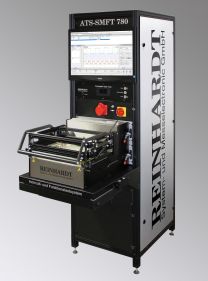
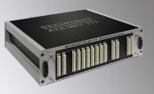
ATS-SMFT 780 In-Circuit and Functional Test System
ATS-SMFT 780 In-Circuit and Functional Test System
SOFTWARE CONFIGURATION:
- Transparent ATS-OS menu-driven software
- Operating system: WINDOWS 10/11®
- Test program wizard
- Graphical display of fault location
- APG automatic program generators
- Autolearn
- Autodischarge
- Multiple printed panel test
- Automatic test program optimisation
- Flashing tools
- Fieldbus communication
- Inline or stand-alone
- RUDC10 CAD-data import
- Software for finding SMT solder defects and software for discerning elcap-polarity
- Test program wizard
- ATSGERB II software for processing Gerber data
- Analysis of testability
- Fixturing construction
- Drilling program for bed-of-nails fixture
- Data for graphical display of fault location
- Analysis of testability
- Quality management
- Statistics-software with failure statistics, repair statistics, histogram, stability
- Traceability
HARDWARE CONFIGURATION:
Twin rack in a 19 " cabinet with work desk 1,420 mm deep, ca. 1,850 mm high
- 1 combined measuring unit
for In-Circuit measurement
- pin contact (contact fault)
- short circuit, isolation (solder defect, interrupt)
- IC and transistor rotation
- components
- measuring DC and AC voltage
- peak voltage up to 100 kHz
- time and frequency measuring unit
periods, pulse widths, rise and fall times, events, pulse ratio and delay, phase measurement, distortion factor, Fourier analysis - transient recorder and much else
- pin contact (contact fault)
- 6 Fixed voltages +5 V, -5 V, +15 V, -15 V, +40 V, -40 V
- 6 Programmable PSUs
- 2 x 0 to +38 V, resolution 1 mV, max. 2 A to 15 V, resolution 50 µA
- 2 x 0 to -38 V, resolution 1 mV, 1 A, resolution 50 µA
- 2 x 0 to +38 V, resolution 1 mV, 0.5 A, resolution 10 µA
- 2 x 0 to +38 V, resolution 1 mV, max. 2 A to 15 V, resolution 50 µA
- Programmable generators
- sine or square wave generator (bipolar)
offset, output voltage/current programmable
max. 1 MHz, resolution 100 mHz
square wave 500 kHz 3db, sine 250 kHz 3db
max. 25 Veff, resolution 1 mV
max. 1 A, resolution 100 µA
pulse duty factor 10-90 %
- pulse generator
0.6 Hz to 10 MHz
pulse width 0.8 s to 50 ns
amplitude programmable from 1.8 V to 5 V
- sine or square wave generator (bipolar)
- 1 potential-free electronic load
- current 0 to 5.1 A, resolution 100 µA, 65 W, max. 90 V
- modulation 10 Hz to 10 kHz
pulse duty factor 5-95 %
- OVP programmable 5 V to 100 V, resolution 1 V
- current 0 to 5.1 A, resolution 100 µA, 65 W, max. 90 V
- 1 Stimulus matrix
- 48 channels
-
12 bus systems
- 1 Logic board
- 32 bidirectionale digital channels
- 30 V
- 32 bidirectionale digital channels
- 5 Measuring matrix
- 96 in-circuit and function measuring channels and guard channels each
-
max. 2,400/3,840 measuring channels
- 1 High voltage measuring matrix
- 8 High voltage measuring channels 420 V
- 8 High voltage measuring channels 420 V
- 1 Powermatrix
- 16 Power matrix channels, 100 VDC, max. 10 A, 70 V ACeff
- 16 Power matrix channels, 100 VDC, max. 10 A, 70 V ACeff
- 1 Transient recorder
- band width 50 MHz, clock rate 250 MSPS
- band width 50 MHz, clock rate 250 MSPS
- Monitoring
- Inline control
- Fixturing control, e.g. contacting on two stages
- Various interfaces
- USB 5 V, 500 mA, 480 MHz
- SPI 2.5 kHz to 10 MHz, 1.8 V to 5 V
- 2x I2C-Bus 56 kHz to 1 MHz
- 2x RS232-interface ±5 V, 300 Hz to 1.25 MHz
- 422/485-intrface 5 V, 300 Hz to 1.25 MHz
- Robotbyte 16 bidirectional, 1.8 V to 5 V, ca. 5 kHz
- Start-Stop box
- Test fixture Type 42C
- working area 360 x 230 mm, incl. protective cover
- working area 360 x 230 mm, incl. protective cover
- Hardware options of ATS-SMFT 780 such as
- solder defect test
- inverse polarity of elcaps and tantal capacitors
- diagnose and calibration unit
- Integration of various bus systems
- Software- modules such as
- REINHARDT Boundary Scan RBS 100
- REINHARDT Boundary Scan RBS 100
* All prices are valid in Germany and the European Community and are without taxes, transport and packing. IE & OE – Specifications subject to change without prior notice.

