New Products
ATS-MFT 770 New Multi-Function Test System
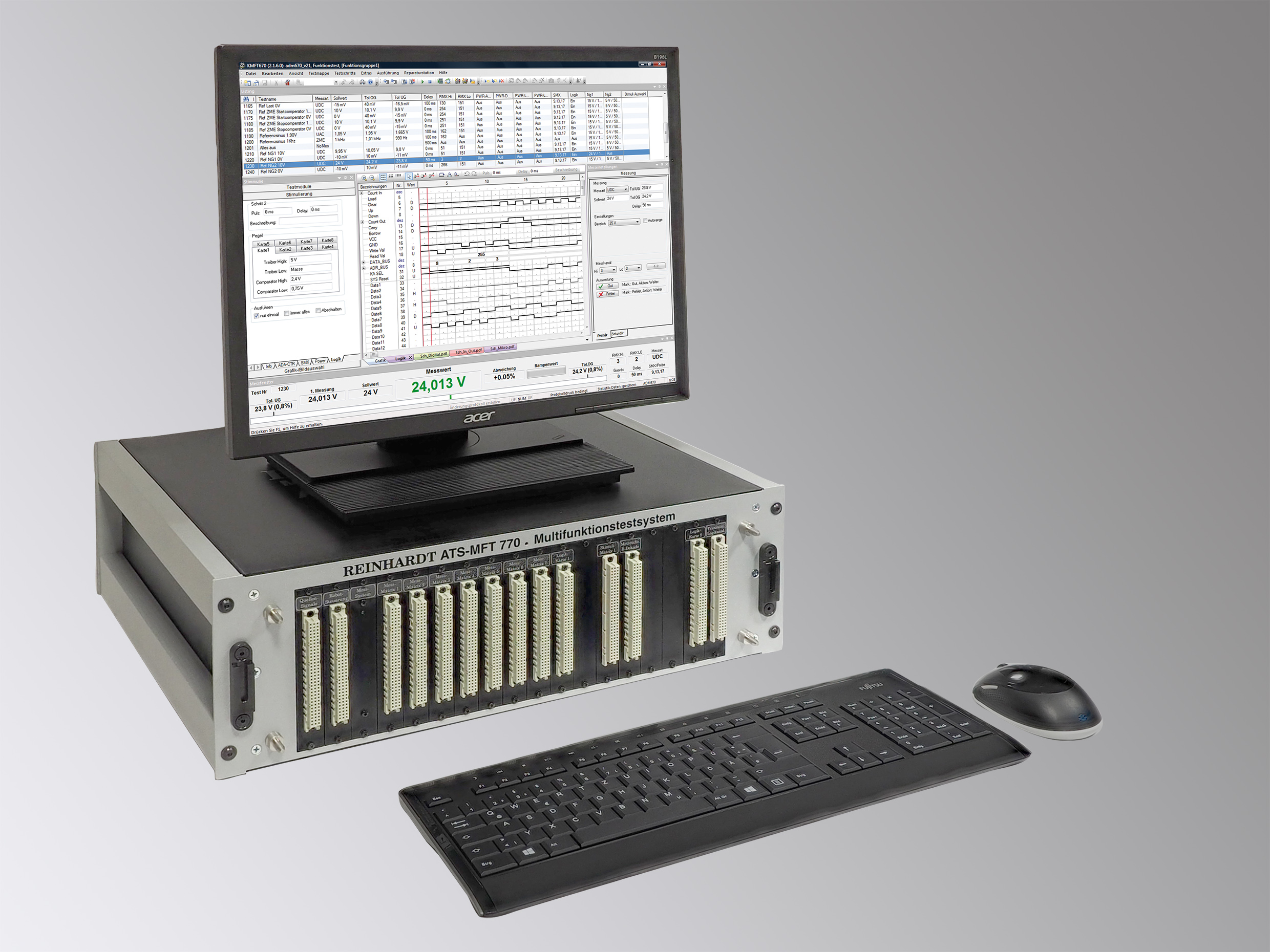
The new ATS-MFT 770M is an In-circuit and Function test system for loaded PCBs, devices, modules and hybrids with all facilities for serial test, inline test, flashing, EOL or use in life expectancy test (e.g. with climatic chamber) or in development.
ATS-MFT 770 is the most powerful combined In-circuit and Function test system that REINHARDT has ever had. The new ATS-MFT 770 offers powerful, programmable multiple PSUs and an electronic DC-voltage load (standard). The promising backplane in the system aims at new technologies and provides higher communication speed as well as higher measuring precision and is also suitable for high voltage and high current tasks.
The test system has extremely short measuring paths which is vital for fast and precise measurements at high test speed.
By standard, ATS-MFT 770 offers USB-, SPI-, 2 x I2C-Bus, RS232-, RS422/485-interfaces and a pulse generator (PWM).
With the new ATS-MFT 770 you can address e.g. 15 RMX 96 measuring matrix boards, that is a total of 1,440 measuring channels and with expansion racks up to 4,320 measuring channels. For coming modules, there is a high voltage bus.
Load product
BOUNDARY SCAN Together with Analog and Digital Function Test
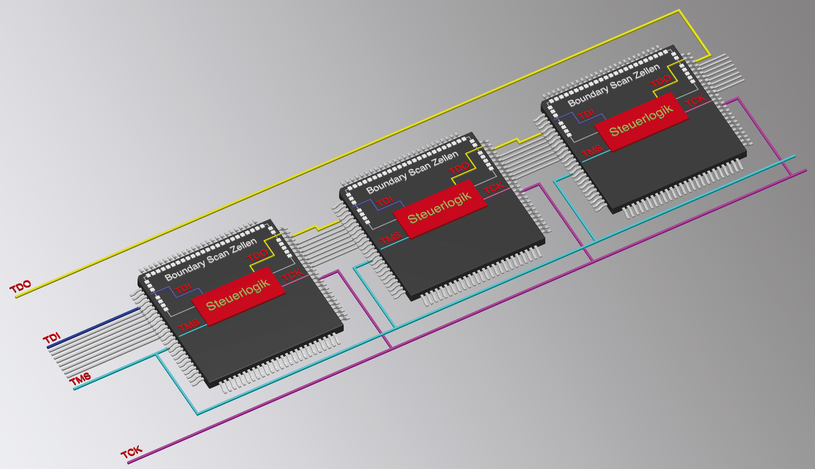 Since Boundary Scan Test was adopted by the IEEE-syndicate in 1990, the short-circuit and interrupt test with the Boundary Scan-method has become an important test method. The PCB under test has been designed and built especially for this test method. The currently used methods operate cryptically and require intensive computer skills and practice in order to create such programs with pretty high cost.
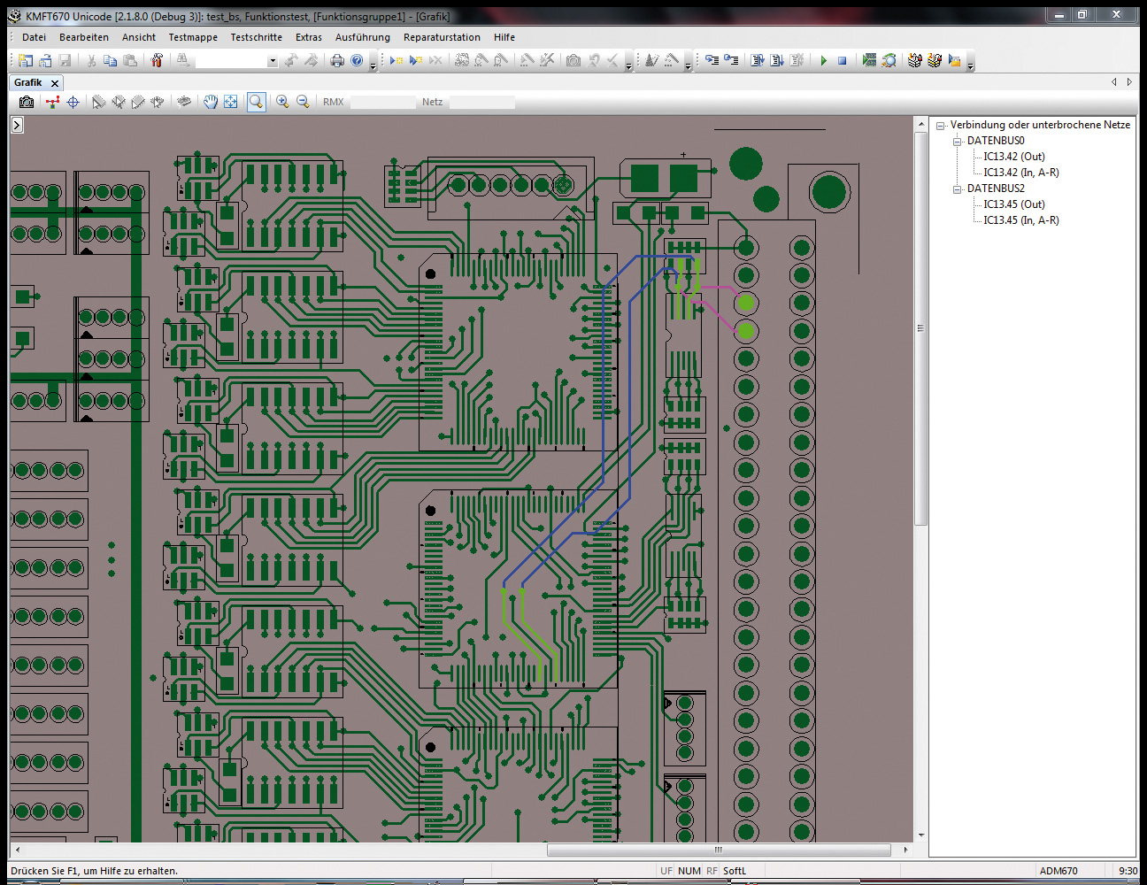 The programs for our test method are mainly generated automatically so that no engineer is required for creating a program in typically 1-2 hours. We have made programming easy and have adapted it to the usual REINHARDT-standard so that skilled workers can program it on their own after 5 hours instruction. As a producer of test systems who provides both in-circuit and function test, we offer evaluation electronics for analog and digital. With that, we execute short-circuit and interrupt test. With the help of serial digital information we generate patterns which then test the function in detail via logic and the logic boards which are connected to the interfaces. This method can also be used for the analog part or for the conversion into serial data such as e.g. interfaces, in order to stimulate them with the data via the Boundary Scan function and measure the resp. tests on the analog side or on the fieldbus side. Of course, it is also possible to feed in analog data via our test system and read and evaluate them via Boundary Scan so that a test of analog input values is possible with Boundary Scan.
In cost and practice-oriented operation we differ enormously from all other products in the market.
Find more
ATS-UKMFT 627 New Combined In-circuit-Function Test System
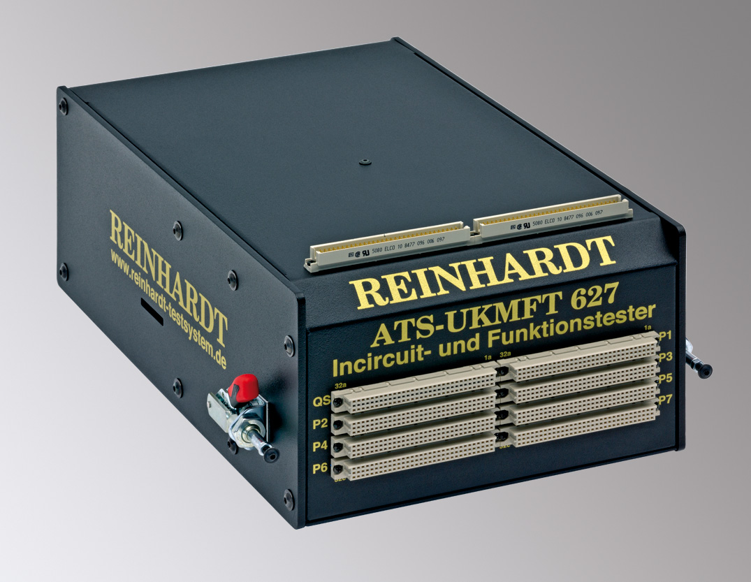 The basic version of the combined In-circuit-function test system comes with 32
bi-directional logic channels, 32 multi-matrix channels and 128
In-circuit- and function measuring channels (expandable to max. 608).
Its in-circuit- and function measuring unit has more than 60 measuring
ranges incl. transient recorder functions and Fourier analysis. 2
programmable, complementary twin PSUs, 0 to 24 V, supply the DUT and
stimulate signals as does the sine and squarewave generator. This test
system is also available with optional test fixtures (working area
192 x 172 mm or 360 x 230 mm) for precise contacting of the PCB.
The basic version of the combined In-circuit-function test system comes with 32
bi-directional logic channels, 32 multi-matrix channels and 128
In-circuit- and function measuring channels (expandable to max. 608).
Its in-circuit- and function measuring unit has more than 60 measuring
ranges incl. transient recorder functions and Fourier analysis. 2
programmable, complementary twin PSUs, 0 to 24 V, supply the DUT and
stimulate signals as does the sine and squarewave generator. This test
system is also available with optional test fixtures (working area
192 x 172 mm or 360 x 230 mm) for precise contacting of the PCB.ATS-UKMFT 627 stands out due to its enormous speed in the practical test speed (typically 3.6 ms per component) and the short time for programming.
As usual high stability and careful handling of the PCBs under test has been a major concern, because many companies do not know that their PCBs are stressed unnecessarily. There are still test systems in the market which apply measuring voltages far above 280 mV to ICs and components. In the in-circuit test this can destroy or damage the component and cause early failures. REINHARDT has found the balance between extremely low test voltage and high currents, very fast test speed, but at high test accuracy. Therefore, other than some competitors, we do not execute the component test in 10-15 % limits and in a comparator window without exact statistical evaluation. Our measuring routines have been developed with the experience of many years and are constantly being worked on in order to reach the best test speed. ATS-UKMFT 627 is not only statistically fast, i. e. that only the theoretically possible test speed per component is summed up, it is also fast in practice with all the conditions of a typical analog-digital component. Test times can be improved by up to 50 % in the latest version, especially for components with a lot of analog technique. That the high speed-measuring unit and the resp. measuring matrix are only 50 mm below the DUT, also results in the fast test speed. For evaluating signals in function test, an own 50 MHz transient recorder can also be integrated. It also benefits from the short connections to the DUT.
ATS-UKMFT 627 can be expanded with the REINHARDT-software modules, such as the new RBS 100 Boundary Scan module. Apart from short-circuit and interrupt test, this boundary scan test can also be used in the analog and digital function test.
Load Product
Load Brochure (640 KB)
TRA670 Transient Recorder (Oscilloscope)
 In testing electronic PCBs, it is necessary to check signals with any curve forms. For many years, this has been done with our TRA470 tranisent recorder which was used to up to 10 MHz. Compared to our new solution TRA670, the TRA470 was less efficient in its operation and convenience.
With 12 bit resolution, 50 MHz band width and samples up to 250 MHz, the TRA670 transient recorder is a lot more efficient than its predecessor. It is used for measuring and graphically displaying signal forms of any kind, from pure sine frequencies, squarewaves, completely free curve forms, distortion factor to Fourier analysis. Frequencies, periods, rise times, fall times, pulse widths and peak voltages can be measured. A special feature of the transient recorder is the envelope curve function. In a default window, the envelope curve can be learnt in a few seconds and can then be corrected and worked on very conveniently: You just touch the envelope curve with the mouse and form it as required. In this way, the envelope curve is modified in a few seconds. Special feature of the transient recorder are its 8 coaxial and 9 high frequency channels with 50 Ω input impedance (each channel can be switched between 50 Ω or 1 MΩ). With the standard measuring matrix, the transient recorder can still be applied to all points. The transient recorder is potential-free so that the signals need not necessarily be measured related to ground. Max. input voltage is 100 V, max. resolution is 250 µV. It is possible to use several TRA670 in a test system in order to measure curve forms in parallel too and display it via an external trigger output.
The TRA670 is another improvement in evaluating curve forms up to 50 MHz and it provides even more test accuracy and test depth for our test. The TRA670 transient recorder can be used in the ATS-KMFT as well as the UKMFT-test system family.
Find more
High Voltage Test in the In-circuit and Function Test
 For many years, In-circuit test and function test used to be in the range between ±15 V. The new technologies and especially the electronization of domestic engineering which are usually 230 V and 400 VAC require new modules which must be tested like the low-voltage current modules. To the contrary, they must be tested so that in the range between 230 V and 400 V neither man nor thing are damaged and the necessary security is ensured.
Our new stimulus matrix boards such as RML32, MMX670 and MMX72 were developed for up to 500 V. HSM670 covers another range up to 1,500 V so that voltages in this range can be stimulated and measured. In a suitable expansion, you can execute cable and wiring measurements up to 1,500 V and currents up to 5 A. The measuring technique of ATS-KMFT 670-5 support the high voltage matrix board and enables you to measure components, harness and devices which create or process voltages up to 1,500 V. The standard ATS-KMFT 670-5 is therefore used for In-circuit test, Boundary Scan test, Function test analog and digital, as well as for wiring test on harness or networks up to 1,500 V. Our comfortable programming is menu-driven and has various program generators. Our programming and the test that follows are as competitive, easy and convenient as no competitor can offer.
Find more
Open Database Connectivity - ODBC-Interface for REINHARDT-Test Systems
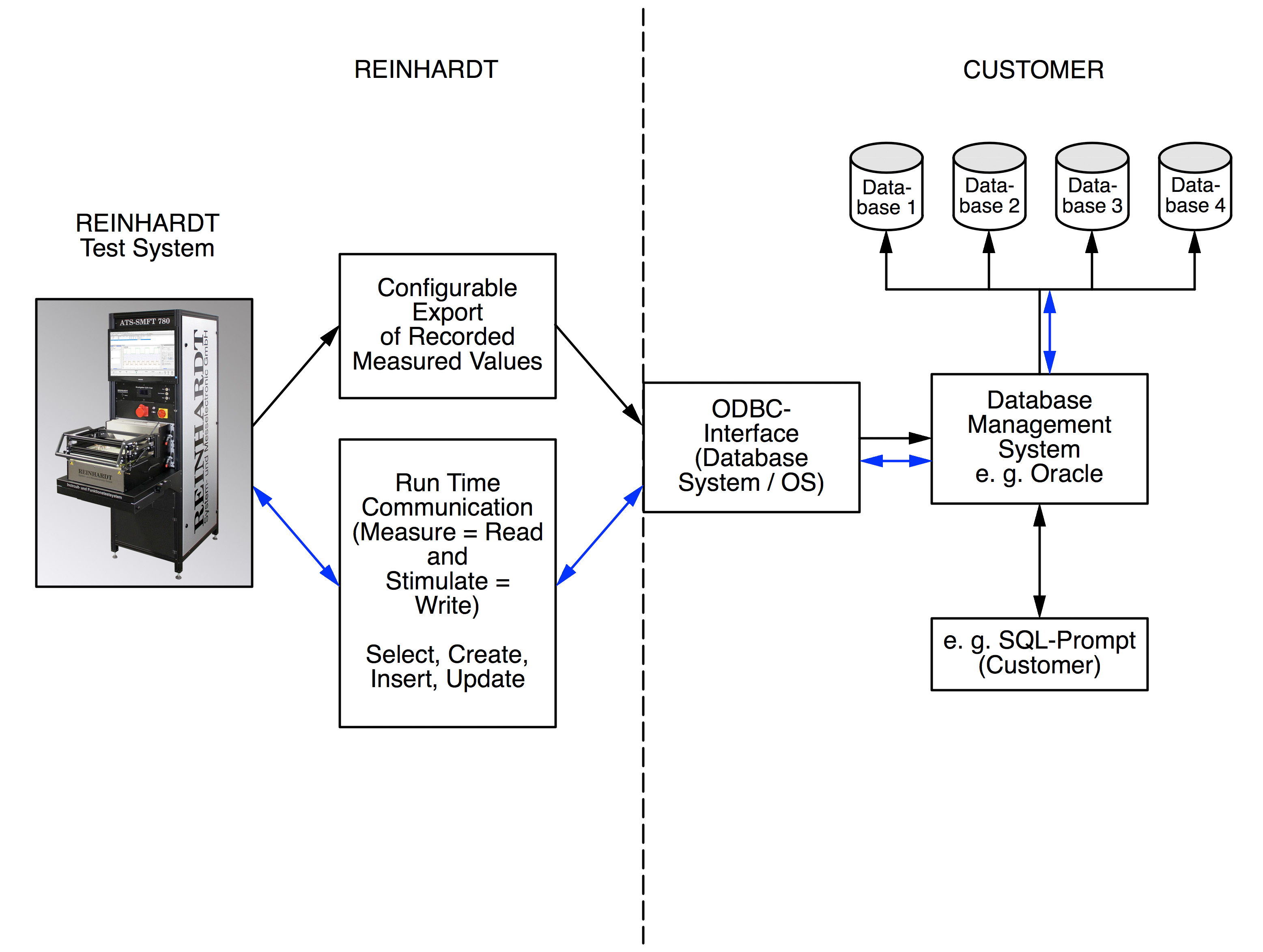 Via this interface the REINHARDT-test system is integrated in quality
management or production procedures with data base management. The data
transfer can be configured so that the data base management system can
process the information for quality management, statistics, etc.
Via this interface the REINHARDT-test system is integrated in quality
management or production procedures with data base management. The data
transfer can be configured so that the data base management system can
process the information for quality management, statistics, etc.The required data base is selected with the ODBC-interface and a connection text is generated. In the test run, this text is used for selecting the data base where the data are stored. Then the table is chosen which stores the data. For that you may use an existing table or generate a new one. When the table is selected, its fields are listed so that only the data sources must be assigned. If the name of a table which does not yet exist is entered, the required fields must be selected and connected to the data sources.
Load Brochure (317 KB)
RUDC REINHARDT Universal File Converter
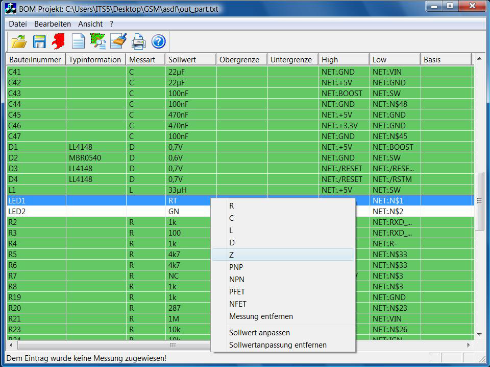 The RUDC Universal File Converter is a universal solution for extracting files from different CAD-systems and processing them for the REINHARDT test system software.
RUDC imports data (e.g. CLP) which are also used for pick-and-place machines. These are component reference (R14, C22), package type (SOT23), value (Value), centre point coordinates (X and Y), top or bottom and orientation (90, 180). The data which were generated with the REINHARDT-software for processing Gerber files are used in addition. After the bill of materials and the data for graphical display of fault location (computed Gerber data) are imported, the automated autolearn tools such as e. g. for pin contact test, shorts and isolation test and the APG in the component editor as well as the component statistics can be used. Conversion of the data is widely automatic and is easy to understand even for inexperienced users
Load Brochure (640 KB)
Test Fixture Production System AAE-CNC 2
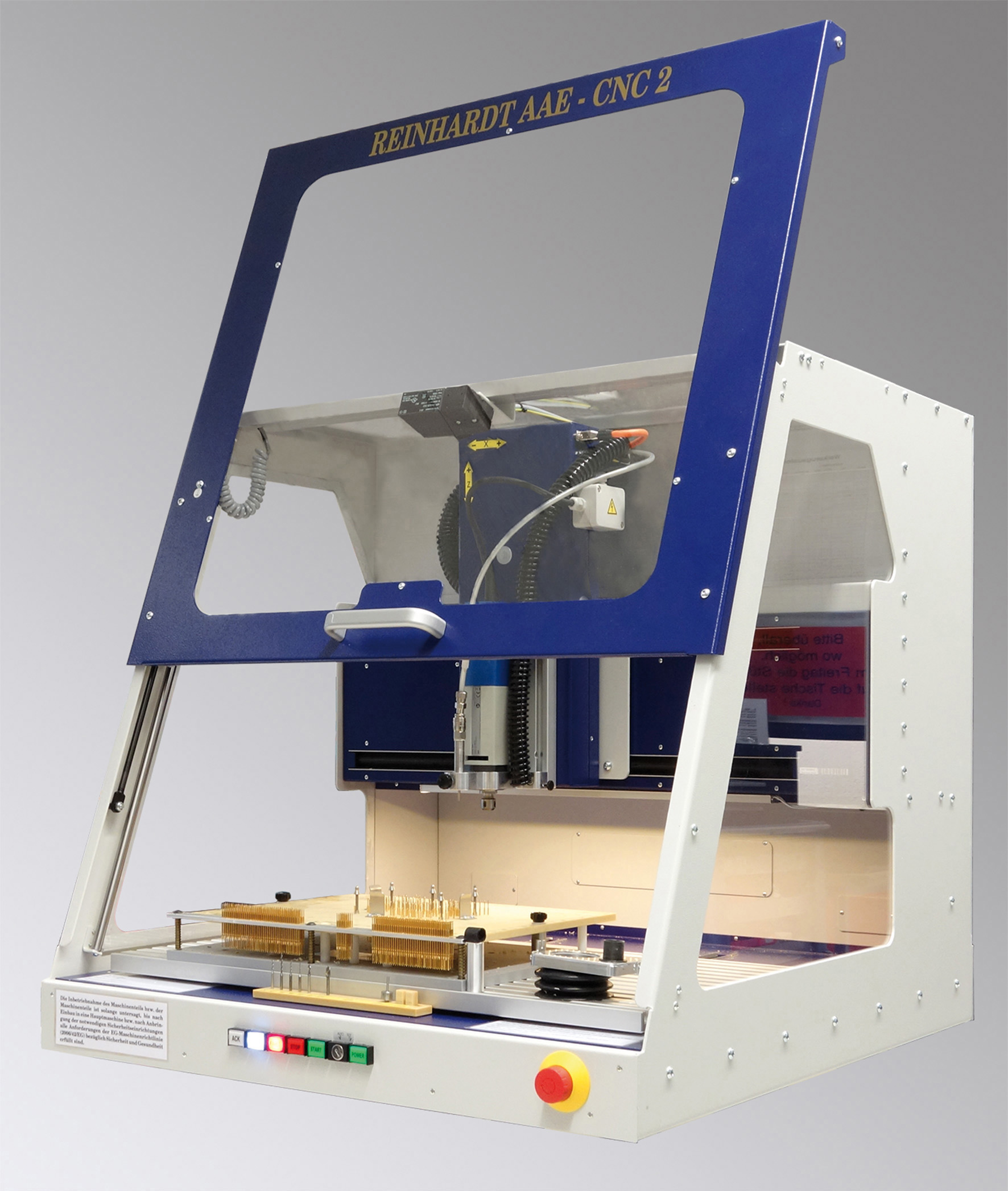 The bed-of-nails-fixture for the In-circuit- and Function test comes last in development and quality management, but it can only be built when the development is completed. If the bed-of-nails is contracted out, it often takes two days to get the functional specification document, documentation and the necessary signatures. Delivery times for a bed-of-nails are typically 3–4 weeks. A lot of time is needed for communication between the customer and the manufacturer of the bed-of-nails.
Our new test fixture production system AAE-CNC 2 enables you to produce a complete in-circuit test fixturing incl. wiring within half a day. You drill the exchange plates of the exchange fixtures for loaded electronic PCBs and place the contact pins automatically. Constructing, drilling and placing the contact pins on the bed-of-nails with typically 10–20 µ accuracy incl. wiring takes a few hours only. The bed-of-nails for the contact pins, reference pins, placing devices, maybe IC-Open-probes and polarity probes are drilled out of the data which were calculated and selected from the Gerber files. No offset or other special entries are required when the test fixture production system is set up. The contact pins incl. receptacle are pressed in very accurately with a special tool which is also controlled by the CNC-machine. Depending on the D-codes the system selects contact pins with different plunger tips from the bipartite magazine. Then comes the wire wrap-wiring. For that there are multi-way connectors which are already wrapped so that only the contact pins must be wired. In this way, a test fixture incl. the calculation times for the Gerber files can be finished in about 4 to 6 hours.
With two to three fixtures a year, the investment will be repaid within one year. With such low cost for a bed-of-nails (often less than 500 Euro original costs) bed-of-nails fixtures are cost-effective even for small series.
Quality Management - Reference Test
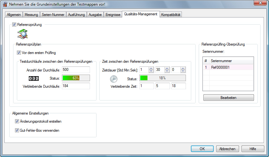 More often, reference tests are specified in testing requirements. Based on a test item which is known to be good, the function of the test system and the fixture must be checked and documented after a specified number of test runs or after a specified time interval. As soon as the number of test runs or the time interval is reached, the test system is blocked and testing can only continue after the reference test.